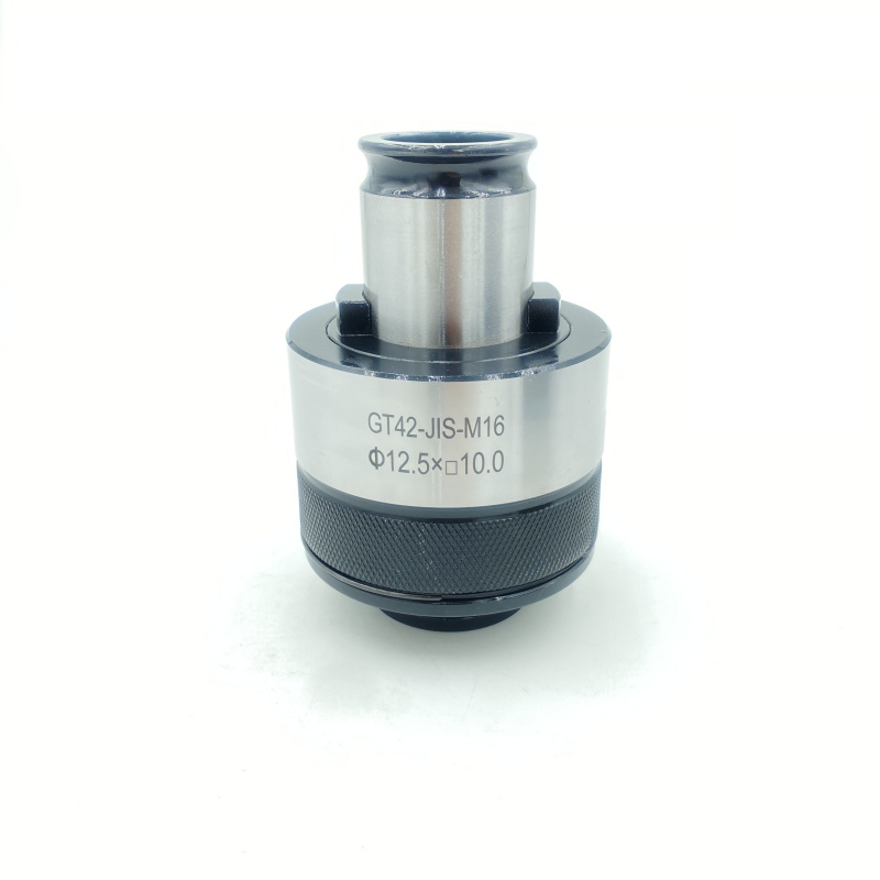
Tap chuck High precision CNC tapping chuck Overload protection design
1. Core performance advantages
High precision and stability
Using precision machining technology, the end face runout can be controlled within 0.003mm, ensuring the coaxiality and surface finish of thread machining.
Elastic or hydraulic structure design can automatically compensate for small deviations, reduce vibration and thread misalignment risks.
Quick replacement and efficient production
The quick-change design allows tool replacement without stopping the machine, reducing auxiliary time and improving processing efficiency.
Standardized interfaces (such as ER, HSK) are compatible with a variety of machine tool spindles to simplify the operation process.
2. Functional design advantages
Overload protection mechanism
Built-in mechanical or hydraulic overload protection device, automatically releases pressure when the cutting force exceeds the threshold to prevent tap breakage and workpiece damage.
Multi-scenario adaptability
Supports tapping requirements for complex working conditions such as blind holes, deep holes, and thin-walled parts, and special groove design optimizes chip removal paths.
It is compatible with a variety of thread specifications from M1 to M30 to meet different processing size requirements.
3. Material and process advantages
Wear-resistant coating technology
Use nitriding, TiCN/TiAlN and other coating processes to improve surface hardness and high temperature resistance and extend tool life.
Anti-corrosion treatment (such as plating or special alloy materials) adapts to humid or chemical environments.
Lightweight structure and rigidity balance
Optimize the connection structure between the chuck body and the tool handle to reduce weight while maintaining high rigidity and reducing spindle load.
Tap chuck: the core carrier of precision tapping technology
In the field of mechanical processing, the tap chuck, as the core tool for thread processing, plays a key role in accurately transmitting torque and protecting the tap. Its design integrates material mechanics, precision manufacturing and process adaptability, and has become an indispensable part of modern CNC machine tools and automated production lines.


Precision of structural and functional design
The core structure of the tap chuck consists of a taper shank interface, a clamping mechanism and an overload protection module. The taper shank interface usually adopts Morse taper (such as MT2/MT3) or ER spring chuck standard, and realizes high-rigidity connection with the machine tool spindle through the principle of taper self-locking, and the end face runout accuracy can be controlled within 0.003mm. The clamping mechanism radially envelops the tap through an elastic sleeve or hydraulic expansion structure, which not only ensures uniform distribution of clamping force, but also automatically compensates for minor offsets during processing, effectively avoiding thread misalignment. Some high-end models also integrate a mechanical torque limiter, which automatically releases when the cutting resistance exceeds the preset threshold, significantly reducing the tap breakage rate.
2. Technological breakthroughs in materials and processes
To meet the needs of high-strength processing, the tap chuck body is mostly forged with 40Cr alloy steel or 20CrMnTi titanium alloy. After quenching and tempering, the hardness can reach 58-60HRC, which has both wear resistance and impact toughness. TiAlN or TiCN coatings are often applied to key contact surfaces to increase the surface hardness to more than 3000HV, and the high temperature resistance exceeds 600℃, which is particularly suitable for continuous processing of difficult-to-cut materials such as stainless steel and titanium alloys. In terms of structural design, a lightweight hollow shaft and stress dispersion groove are used to reduce the weight by 20%-30% while ensuring rigidity, reducing the spindle load during high-speed rotation.
3. Engineering innovation for multi-scenario adaptation
For different processing environments, tap chucks have derived specialized variants: the blind hole tapping type can penetrate into blind holes with a hole depth ratio of 5:1 by shortening the chuck length and optimizing the chip removal channel; the multi-axis synchronous processing type is equipped with a CT series indexing plate interface, supporting 4-12 chucks to rotate synchronously, increasing the efficiency of batch thread processing by more than 3 times. In the field of automation, the intelligent chuck equipped with an M12 electrical interface can provide real-time feedback on the clamping status and torque data, forming a closed-loop control with the CNC system to achieve process optimization for unmanned production.
| Thread bottom hole drill diameter(metric coarse thread) | |||||||
| Thread specification | M1×0.25 | M1.4×0.3 | M1.8×0.35 | M2×0.4 | M2.2×0.45 | M2.5×0.45 | M3×0.45 |
| Drill bit diameter | 0.75 | 1.1 | 1.45 | 1.6 | 1.75 | 2.1 | 2.5 |
| Thread specification | M4×0.7 | M5×0.8 | M6×1 | M8×1.25 | M10×1.5 | M12×1.75 | M14×2 |
| Drill bit diameter | 3.3 | 4.2 | 5 | 6.8 | 8.5 | 10.3 | 12 |
| Thread specification | M16×2 | M18×2.5 | M20×2.5 | M22×2.5 | M24×3 | M27×3 | M30×3.5 |
| Drillbit diameter | 14 | 15.5 | 17.5 | 19.5 | 21 | 24 | 26.5 |
| Thread specification | M33×3.5 | M36×4 | M39×4 | M42×4.5 | M45 | M48×5 | |
| Drill bit diameter | 29.5 | 32 | 35 | 37.5 | 40.5 | 43 | |
| Thread bottom hole drill diameter(metric coarse thread) | |||||||
| Thread specification | M3×0.35 | M4×0.5 | M5×0.5 | M6×0.75 | M8×1 | M8×0.75 | M10×1.25 |
| Drill bit diameter | 2.7 | 3.5 | 4.5 | 5.3 | 7 | 7.3 | 8.8 |
| Thread specification | M10×1 | M10×0.75 | M12×1.5 | M12×1.25 | M12×1 | M16×1.5 | M16×1 |
| Drill bit diameter | 9 | 9.3 | 10.5 | 10.8 | 11 | 14.5 | 15 |
| Thread specification | M20×2 | M20×1.5 | M20×1 | M24×2 | M24×1.5 | M24×1 | M30×2 |
| Drill bit diameter | 18 | 18.5 | 19 | 22 | 22.5 | 23 | 28 |
| Thread specification | M30×1.5 | M30×1 | M36×3 | M36×2 | M36×1.5 | M42×4 | |
| Drill bit diameter | 28.5 | 29 | 33 | 34 | 34.5 | 38 | |
| ISO529-GT12 | Tap shank diameterxsquare head size | D | D1 | L1 | L2 | Power range | H |
| M1-M2 | 2.5x2 | 19 | 37 | 22 | 26 | M1-M10 | 10 |
| M2.2-M2.5 | 2.8x2.24 | ||||||
| M3 | 3.15x25 | ||||||
| M4 | 4x3.15 | ||||||
| M5 | 5x4 | ||||||
| M6 | 6.3x5 | ||||||
| M8 | 8x6.3 | ||||||
| M10 | 10x8 | ||||||
| ISO529/2283-GT12 | Tap shank diameterxsquare head size | D | D1 | L1 | L2 | Power range | H |
| M3 | 2.24x1.8 | 19 | 37 | 22 | 26 | M3-M16 | 10 |
| M4 | 3.15x2.5 | ||||||
| M5 | 4x3.15 | ||||||
| M6 | 4.5x3.55 | ||||||
| M8 | 6.3x5 | ||||||
| M10 | 8x6.3 | ||||||
| M12 | 9x7.1 | ||||||
| M14 | 11.2x9 | ||||||
| M16 | 12.5x10 | ||||||
| ISO-GT24 | Tapshank diameterxsquare head size | D | D1 | L1 | L2 | Power range | H |
| M5 | 5x4 | 30 | 57 | 30 | 40 | M5-M30 | 12 |
| M6 | 6.3x5 | ||||||
| M8 | 6.3x5 | ||||||
| M10 | 8x6.3 | ||||||
| M12 | 9x7.1 | ||||||
| M14 | 11.2x9 | ||||||
| M16 | 12.5x10 | ||||||
| M18 | 14x11.2 | ||||||
| M20 | 14x11.2 | ||||||
| M22 | 16x12.5 | ||||||
| M24 | 18x14 | ||||||
| M27 | 20x16 | ||||||
| M30 | 20x16 | ||||||
| IS0529/2283-GT42 | Tap shank diameterxsquare head size | |D | D1 | L1 | L2 | Power range | H |
| M24 | 18x14 | 45 | 85 | 48 | 68 | M24-M42 | 20 |
| M27 | 20x16 | ||||||
| M30 | 20x16 | ||||||
| M33 | 22.4x18 | ||||||
| M36 | 25x20 | ||||||
| M39 | 28x22.4 | ||||||
| M42 | 28x22.4 | ||||||